Showing posts with label Electronics. Show all posts

Tuesday, July 30, 2013

Last minute building

Had trouble finding time to build R6 and update this blog due to being very busy at work this past month.  but now I'm on vacation this week for Droid-Con 2.  Let the games begin.

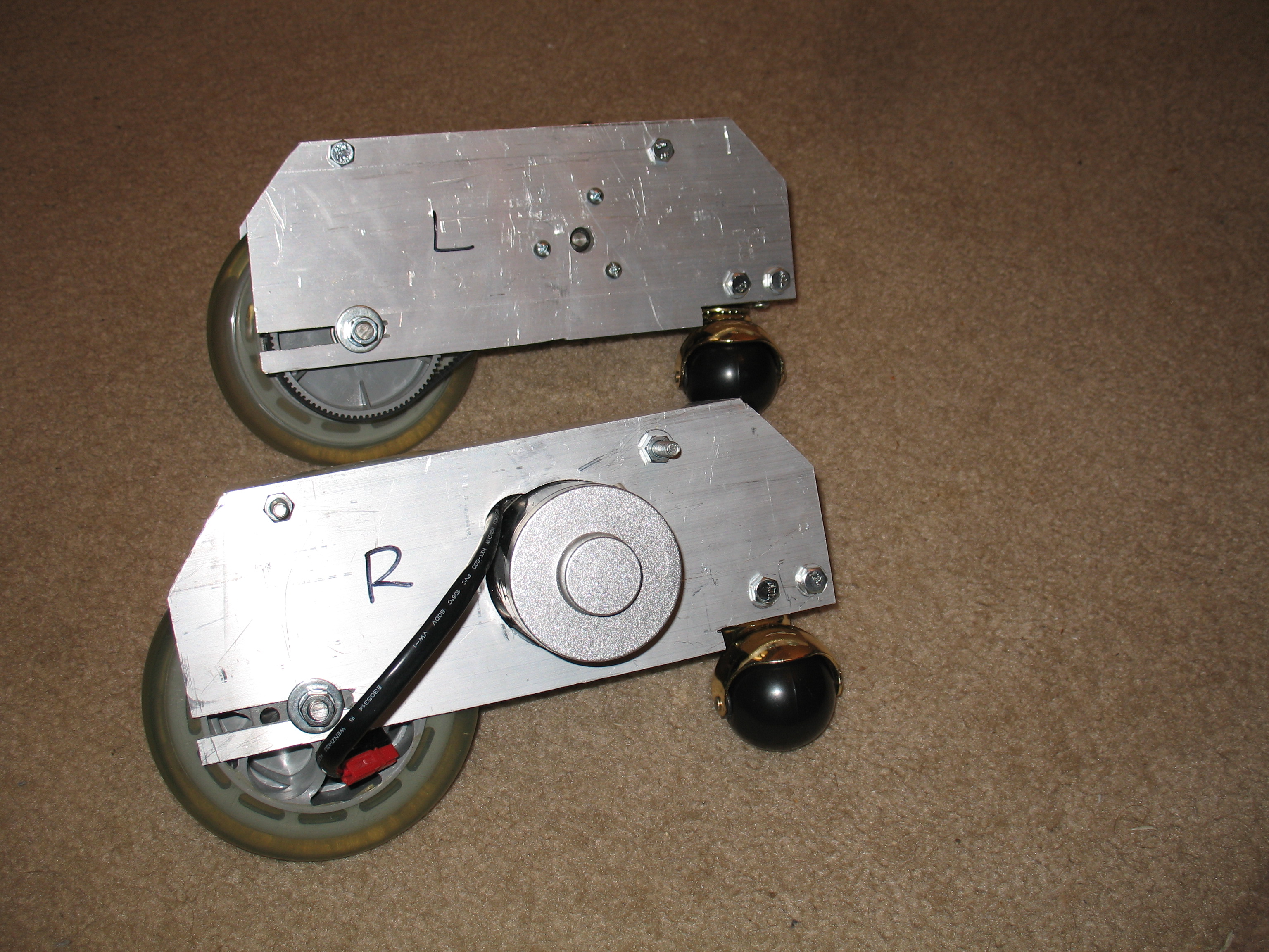
Version 2 foot drives are now complete, assembled, installed and tested.


It's a bit sluggish on the carpet, but I think I can fix that by tightening the drive belts a little more.

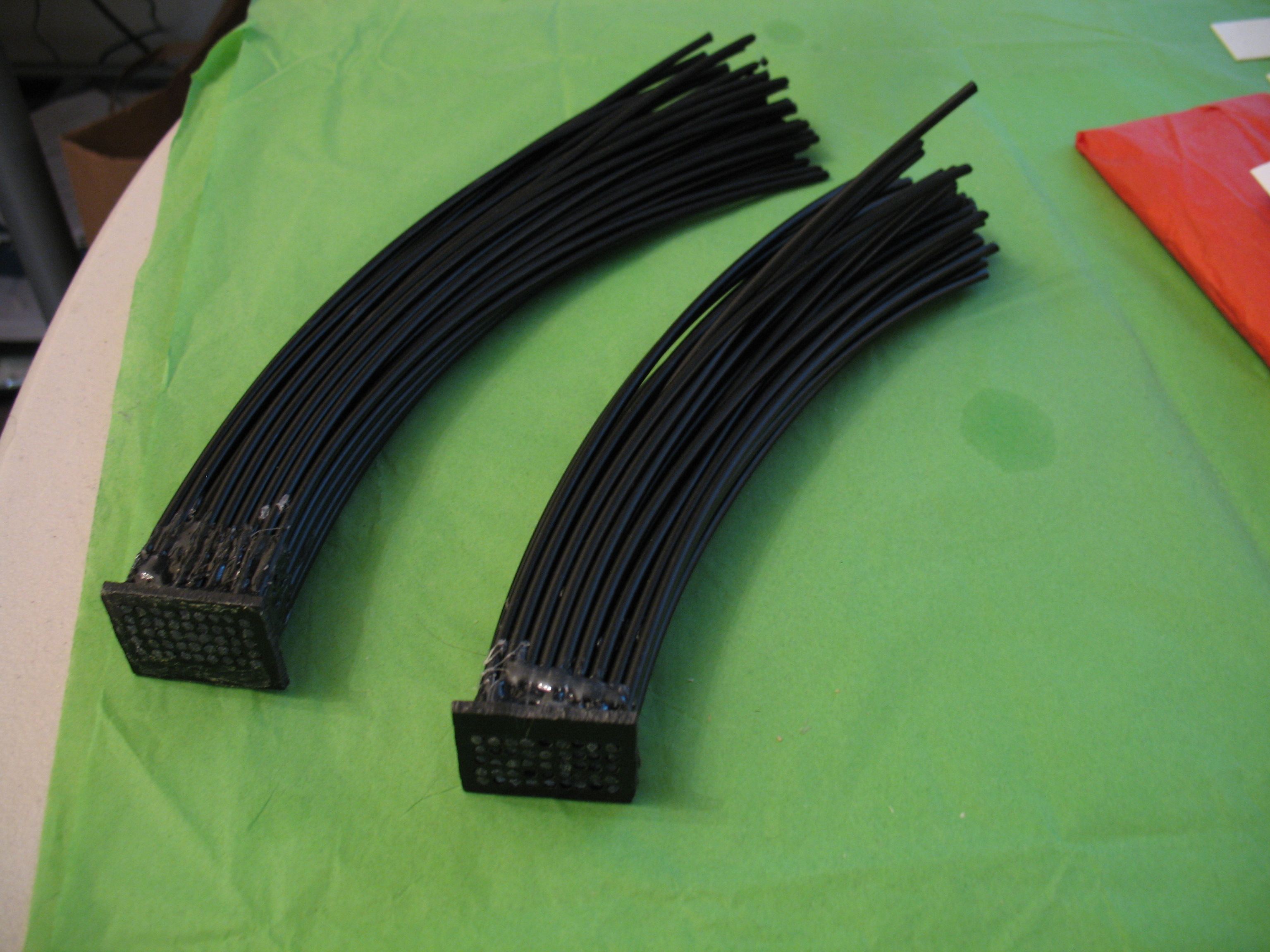
In addition, I've started working again on the Logic Displays.  My big road block of late has been securing the fibers in the bezels.  Recently it was suggested to me to try using a hot glue gun.  Amazingly that worked perfectly.  I now have both halves of the Front logic Display fibered up and ready for installing.


But before I do that, to give the logics more depth, I glued in another piece of styrene behind the logic cutouts in the head.  When dry, I'll cut out the holes, fill the seams and then install the Front Logics.

To fill in all the gaps and seams on the head, I'll be using a product used for minor automobile body repair, Bondo.  I've never used this stuff before but I'm told it's the best stuff to use for this purpose.

This weekend is the 2nd annual Droid-Con!  If you're coming, see you there.  Of course I'll be taking some video and pictures.

John.

Friday, May 11, 2012

Painting HP's, Logic Woes

Today I sprayed on a third coat of paint onto the body skin panels and a first coat of aluminum paint onto the Holoprojectors.  Very happy with the results.


I'm having trouble getting the fiber optic strands to stay put in the templates.  The silicone idea didn't work out so I'll need to do a little brain scrubbing for a better idea.  Maybe you have one?

John

Tuesday, May 8, 2012

Logic Display Templates

Yesterday I finally made the Logic Templates, the little boards with holes cutout of them for the fiber optic strands to stick through.  I used a piece of Acrylic.  It has paper on each side to protect the surface since the surface is very smooth and glossy.  This worked to my advantage as the paper gave me a surface to easily draw the templates onto.


After cutting out each piece, I used my Dremel Drill Press to make the holes.  Here's some math for you.  the front logics are made up of 2 5x9 grids for 45 points of light each, or 90 all together.  The rear logic is one 4x27 grid for 108 points of light.  All together I drilled out 198 3/32" holes.  Lots of fun!

Now for the fun part.  Threading each little hole with a strand of fiber optic cable.  I tried to start it last night but as I went along some of them kept falling out.  To solve this, I'm going to try to secure a few at a time.  I'll start with the front logics since I already have the fiber optics cut for them.  I ordered more fiber for the rear logics which should arrive in a few days....I hope.

Started painting the last two body panels.  Also did an aluminum color test on a piece of styrene.  Want to make sure I get the desired results for the HP's.

Another Midwest Builders Gathering is coming on June 2nd.  I hope to have the logics and PSI's temporarily mounted for it plus having the Radar Eye mounted.  Also, Celebration VI only 4 months away!

John

Monday, May 7, 2012

Holes and Paint

Yesterday I accomplished drilling the holes for the PSI's and the Holographic Projectors (HP's), and started priming the HP's and the two remaining skin panels.


I'm using a different primer than before.  This time I decided to try using an automotive wet-sandable primer.  It's also very fast drying so I can sand and prime it after only 4 hours where before I had to wait 48 hours.  Today I'll give the parts one more layer of primer then when dry, a first coat of paint.

Other work I did yesterday was sand down the PSI LED caps to fit the inside curvature of the head.  To do this I taped 150 grit sandpaper inside the head and then started rubbing the PSI LED cap against it.  It took a while, but I finished both caps.  Then I cemented the PSI lenses to the caps.  The PSI lens material is from a gallon milk jug.  The MacGyver way to built a droid, hehe.


The resin Radar Eye was designed to fit an R2 shaped dome.  My R6 head, however, is shaped a little differently.  Do to this, I have to modify the Radar Eye to fit my R6 head's curvature using the same method I used for the PSI's.


I spent over an hour last night rubbing the Eye and it's close, but I realized I still need to fit the lens for the eye behind it.  Will be examining the fit of these pieces to ensure proper look and fit.  Work in progress.

More updates to come.  May not post them until next weekend.  Stay tuned.

John

Monday, April 2, 2012

Time Flys

I just noticed I haven't posted anything since January. Please pardon my absence. I've been busy getting up to speed with a new job I started in January.

Sadly I haven't done anything new since my last post. I'm planning to real soon. Just dealing with a lot of work and little money to spare.

Speaking of money, my "Funds for Celebration VI" progress is $0.00. Though I've been trying to save money since last August, stuff keeps happening requiring money. At this point it's not looking promising I'll be able to put aside enough money. But there is still a chance. As long as nothing happens within the next five months, I should be able to put aside just enough money for the trip. Fingers crossed.

Coming up soon (I hope): I still have two body skin panels to repaint plus painting the main skin panels themselves. Also finishing the head. Just one more main piece of styrene (plus the two top pieces), paint and lights and it's done.

Spring time is building time.

John

Saturday, January 7, 2012

Nearing the Finish Line

OK, boys and girls. We are getting close to being done building the head....finally!

I've been working on this for the past week so lots to show you. Not only do I have the electronics tray installed, but I've started adding the skin as well.


So here's the head with the electronics tray mounted. I even have the Logic LED Tubes mounted, just need the fiber optics now. I put connectors on the PSI wires so I can disconnect them if needed.


I soldered wiring to the PSI LED's and then used heat shrink to protect the solder joints. Once I have the skin done I will mount these and connect them to the PSI circuits.


I used a triangle hinge to mount the tray to the head and a single screw to hold it closed. With the main switch on the bottom, I shouldn't need to open it except to replace the batteries and/or do maintenance. Works pretty well I think.


This clamp is holding the neck piece of styrene while it drys at the seam. Had to cut two pieces before I got it right. Once this is dry, I'll test fit the main piece but I don't want to glue it on until I get the fiber optics finished. Trying to install the fiber optics after all the styrene pieces are on will be next to impossible. However, I've already cut the main piece and it looks like it will fit well. I'll know for sure once I get that clamp off.

Should have more to post soon.

John.

Sunday, January 1, 2012

First Post of the New Year with Head Work

HAPPY NEW YEAR! 2012!

So I'm sitting at home playing my new favorite game, The Old Republic, all the while R6-C9 is sitting next to my desk, and I can't help but start thinking between killing Sith Lords and such how to solve various droid building puzzles, such as fitting all the electronics into R6's head, when I start having a brain storm and next thing I know I'm off to the shop to make one little wooden piece and drill a few holes and....well....in a span of 3 hours (give or take) I made an electronics mounting tray for the head. Check it out.

So I got thinking about how easy or difficult it will be to work on the head's insides so I thought a removable tray like the body has would be ideal. Thus I came up with this:

This is the piece I cut out from the bottom of the new head. I thought, "it will fit perfectly and there's plenty of room to mount all the techno stuff."

The Processor State Indicator (PSI) circuits.


That hole is for the main power switch for everything in the head. Typical me, I didn't think to drill the blasted hole until after I started mounted the PSI's. Silly me. Had to remove them so I could drill the hole. The wood is 3/4" thick so I had to drill a larger hole most of the way through so I could mount the switch.


This is for a set of sub-power switches so I can turn off each component if needed. Most of the time they'll stay on and I'll just use the main switch.

PIC LED Flasher circuits for the Logic Displays mounted.

Sub-Power Switches installed.

Everything wired. This setup will use two 9V batteries connected in parallel for double the amperage. All the black wires are tied together while the red wires connect the switches in parallel to the main switch. I'll make a schematic some day to help that mess of wires make sense.

Next up is connecting the tray to the head in an easy to remove fashion. Wish me luck.

John

Sunday, September 11, 2011

Back Log of Updates

Sorry I haven't posted in a while. I have been working on R6, but work has kept me busy and so I've been putting off posting updates. So get ready to be bombarded with progress.


First bit of news is the upcoming Mid-West Droid Builders gathering in northern Indiana this weekend. To prepare I've been repainting the feet, rebuilding the center ankle and repairing the wiring from everything that happened at Droid-Con last May. Wiring is done and the new center ankle will be ready as soon as the glue drys and I drill the mounting holes. The Feet are primed and just need to be painted and clear-coated.
Photobucket

And now some progress on the Logic Displays. Wait....what? The Logic Displays?! Really? An actual update on the Logic Displays?! Yes, it's true. It's been awhile hasn't it. But don't get too excited. It's not much. All I did was drill a hole.
Photobucket
This hole is where the fiber optic strands will fit into the LED tube. All that's left now if to make a block to fit each cord of fiber into so they're arranged correctly. Just need a flat board of black ABS plastic.

Most of my work this past month however has been on the head. Shortly after my last post, I finished cutting the ribs and did a test fit.
Photobucket

So far so good. But before I start gluing it all together, I finally bought my first sheet of Styrene, a PVC type of plastic commonly used in professional sign making and related things, to perform a test fit to make sure the plastic would retain a smooth circular shape when wrapped around only four ribs. It's a good thing I did this because the test failed. At first I thought I needed to add more ribs. But then I tried the same piece of styrene on the original head and it wrapped around perfectly. The reason is because the original head has rings going around it that help the styrene maintain a smooth bend around it. So that's what I needed to add to head v2.

I decided I needed to add a ring to the middle and the top of the head. I will use 1/4" wood and will sand the edges to the same angle as the outer edge of the ribs where the rings will be. The middle ring will need to be two 1/4" rings glued together like a sandwich with each ring's edge angled differently to match the face/neck angles (very much like the original head).

Here I'm cutting out the middle of the middle ring. Both 1/4" halves are already glued together. I'm making each ring only 1" thick from outer to inner circumference. The notches on the inside are to fit into the notches I put into the ribs.
Photobucket Photobucket

The ribs with the notches for the rings cut into them.
Photobucket

Here's the head assembled with the top ring and a close-up of how it fits together. Not a perfect fit but close enough.
Photobucket Photobucket

On Tuesday I will test fit the middle ring and drill the mounting holes into the center ankle. If all goes well I will be able to glue the head together.
One more thing I need to do is make the ankle lock for the center foot so it doesn't tilt when moving backwards.

John

Tuesday, July 5, 2011

Happy Independence Day

Well, the fourth of July was yesterday, but better late than never.

I've been busy at my new job so I haven't had much free time (or money) to devote to R6-C9. But I got a three day weekend this holiday so I was able to find a little bit of time to continue building.

Finally got the holes drilled to mount the head motor on the other side of the body. Looks like it'll work. Now I just need to install longer wiring on that side of the body for the head motor (existing wire isn't long enough).
Photobucket Photobucket

My first attempt at remaking the center ankle didn't turn out very good so round 2.
Remake of center ankle

Now about the head. I have confirmed the top of the head is wider than it should be. It's wider by about 1/2" to 3/4". How I did that I don't know. It doesn't match the notes I made during it's construction. As for the full scale layout I had printed, i recently discovered it is 1/8" smaller than it should be. That's the last time I go to Kinkos to have something this big printed. So after compensating for the scale difference, I have determined the correct diameter of the top of the head. Instead of trying to modify my existing head, I'm going to make a new one, and this time I'm taking a different approach to it. I'm going to make eight vertical ribs made to be half of one full side of the head. I will place these on a disc in a circle and then wrap them with styrene.
Photobucket

I'm going to try to make time to work on this at least once a week. Hopefully I can have the head mostly done before next year. The head is going to be my primary focus until it is finished.

John