Had trouble finding time to build R6 and update this blog due to being very busy at work this past month. but now I'm on vacation this week for Droid-Con 2. Let the games begin.
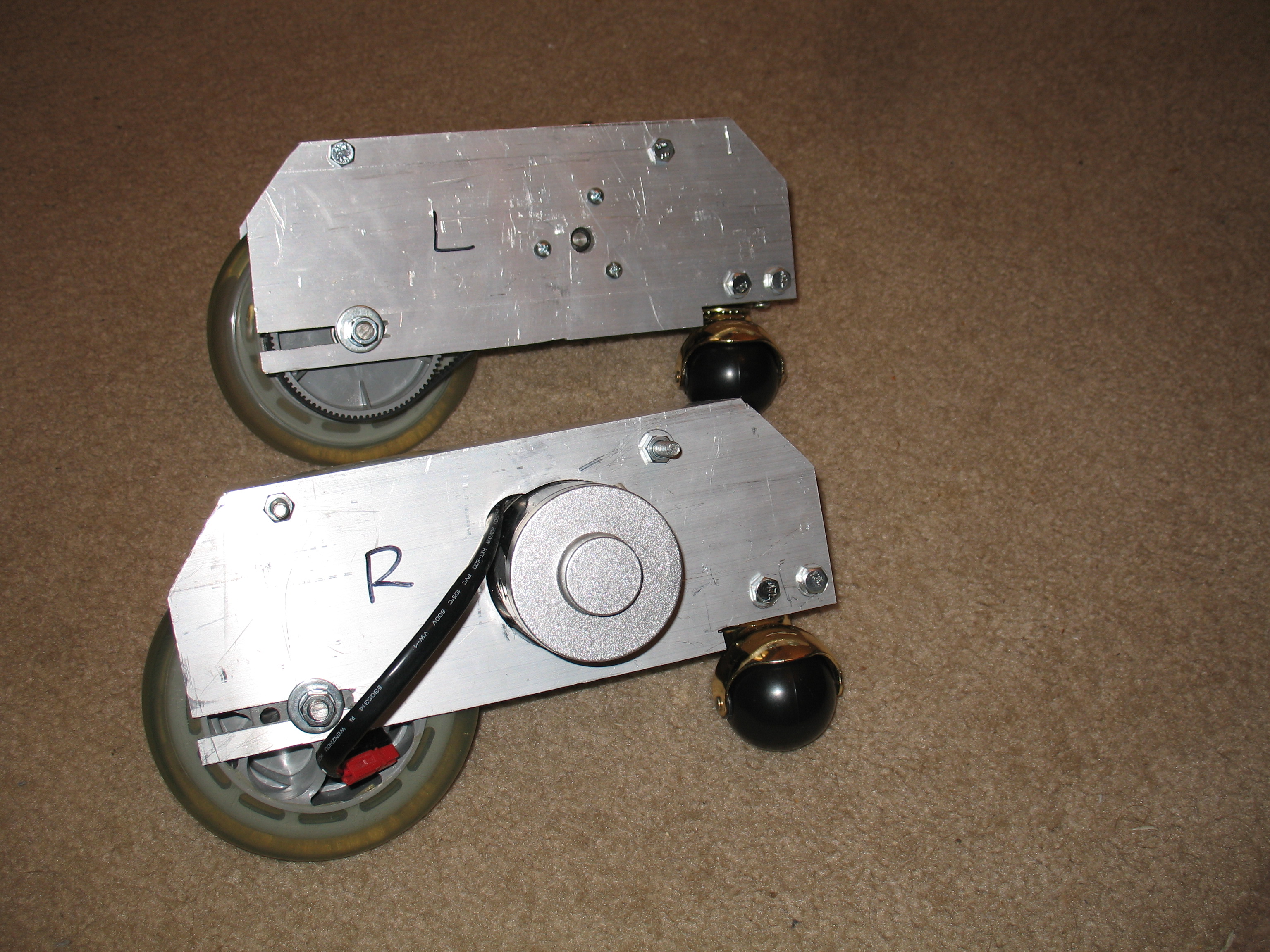
Version 2 foot drives are now complete, assembled, installed and tested.
It's a bit sluggish on the carpet, but I think I can fix that by tightening the drive belts a little more.
In addition, I've started working again on the Logic Displays. My big road block of late has been securing the fibers in the bezels. Recently it was suggested to me to try using a hot glue gun. Amazingly that worked perfectly. I now have both halves of the Front logic Display fibered up and ready for installing.
But before I do that, to give the logics more depth, I glued in another piece of styrene behind the logic cutouts in the head. When dry, I'll cut out the holes, fill the seams and then install the Front Logics.
To fill in all the gaps and seams on the head, I'll be using a product used for minor automobile body repair, Bondo. I've never used this stuff before but I'm told it's the best stuff to use for this purpose.
This weekend is the 2nd annual Droid-Con! If you're coming, see you there. Of course I'll be taking some video and pictures.
The wheel I ordered for the head motor arrived Friday and I wasted no time installing it.
I got the wheel from ServoCity.com. They actually send you two wheels. In addition I had to order a 1/4" wheel hub to attach it to the motor shaft plus screws.
Video shows the wheel working without and with the head on. Another long awaited mile-stone reached.
It's a good thing I got a stronger tension spring. I tried it with the first one I got and it wasn't pulling the bracket hard enough for the wheel to get good traction on the Rockler bearing. Using a shorter and stronger spring fixed that.
I also received shipping conformation for the belt wheels with am estimated arrival time of "varies." God willing the wheels will arrive in time for me to install them before Droid-Con.
Yesterday I continued work on the Center Foot's caster mount. After test fitting the block I made I discovered I had miscalculated and ended up being a full one inch short. So I had to make two more half-inch blocks and glue them on.
Next I started work on the mounting bracket for the head rotation motor. Using scrap aluminum from the foot drive brackets, I made a flat piece measuring 1-1/2" x 4-1/2" x 1/8". I then drilled two holes to mount the motor, one hole for the motor shaft, one hole to mount the bracket to the body frame, and one more to connect a tension spring to. The tension spring's purpose is to pull the wheel (that will be on the Pittman motor) snug against the inside of the Rockler bearing. The other end of the spring simply connects to a hook of some sort on the body frame. To secure the motor to the bracket the motor is pre-tapped for #10-32 machine screws. To secure the bracket to the frame I'm using a 5/16" x 1" hex-bolt with 2 metal washers and three nylon washers. The nylon washers go right above and below the bracket. They help the bracket move while the bolt is tight. For the spring I used spare screws I had laying around.
Two things. One, I feel the spring I got is too long to give the amount of pull I want so I'm going to get a shorter one. Two, in the last photo you can see a half-circle drawn where the motor shaft is touching. This is where I need to remove some material so the motor can be close enough so the wheel will touch (I'm just a few fractions of an inch off). This Thursday I will take the body to the shop and carefully remove that spot. Hopefully the wheel will arrive by then so I can do a full test fit and then a powered test run.
When I was assembling R6 at Celebration V, I discovered the bolts which hold the ankles to the feet wouldn't fit through the holes in the feet. The bolts were the correct size, but the holes were just a bit small. So yesterday I fixed that by using my Dremel with a small sanding drum to widen the holes a bit. Now the bolts will fit so the legs and feet can be securely connected.
While I was at the shop I started working on a new head for R6. The main problem with the current one is the crown, or lack there of. I had thought I could add it on later but my attempts to do so have fallen short in good results. So my new design for the head will be to made the vertical ribs one whole piece, including the crown. I'll be making 6 ribs (fewer than the current head has) mounted to a base that will sit on the rockler bearing. My first attempt at making the first rib leaves some room for improvement but with a few adjustments it should work this way. Once assembled I will continue as originally planned and wrap the head with styrene or sintra (both are similar types of PVC based plastic). Can I get all that done before Droid-Con? Maybe, but I'm more eager to get the foot drive system finished first.
Speaking of the foot drive, I ordered the aluminum tubing and it should be here any day. Maybe Sunday I can start on that.
Finally got more priming done of the feet. They are now completely covered in primer. If the weather is good this Thursday, I'll start using the actual paint.
For the Celebration V, it turns out George Lucas will be attending again. This makes only his third appearance at a Star Wars convention, the last one being Celebration III. Hopefully he can grace the droid builders room with his presence once again.
I know I said the last color scheme was locked in for R6, but I have decided to change it....again. It's a darker blue and in different places than R2-D2. Every time I think "R6-C9" I think "blue." I only resisted before because I didn't want to chance him being mistaken for R2-D2. But with this design, I think it'll be ok.
One more thing. I might rebuild the head. After rechecking some things, I found I made the top a half-inch too big. Not that there's an official R6 design to base that off of, but the plans the club is using suggest that measurement. It's still something I'm only thinking about. If I decide to remake it, I'll wait until after the convention.
This is version 2 of the PSI circuit I made a loooong time ago. This one is printed instead of little wires connecting all the componets. Also, the LEDs will be separate from the pcb instead of attached to it. Have yet to test it.
Using my Dad's Shop Smith Mark V in drill press mode (sounds like something from the power rangers doesn't it, "Mark V Megazord Drill Press Mode!!! Hiyaa!"). I'm drilling holes into the outer ring of the Rockler Bearing so I can attach it to the top of R6's body. I used a 3/16th" drill bit. Be sure to put masking tape over the gap between the inner and outer rings to keep metal shavings from getting into the bearings, a MUST do.
The Rockler Bearing comes in various sizes and is available at McMaster-Carr. The size we use in the Club is the 17-3/8". Use the outer ring for the body and the inner ring for the head.
Here I'm checking the measurment all the way around the Rockler to ensure it's perfectly centered on the bottom of the head.
Used #10 1-1/4" wood screws to secure the inner ring to the head. Note that the inner ring already has six pre-drilled holes.
The Rockler Bearing sitting on the upside-down head. The white dots are little rubber standoff feet. Keep these in place.
You don't want to perimently attach both rings of the bearing so you can remove the head. Normaly the outer ring is attached to the body and the head is placed on top of it. But because of the way my wood head is designed, I have to reverse this setup. So I put four #10 1-1/2" metal bolts, secured with nuts, into the holes I drilled. These will be pointing down and will slide into four holes in the top of R6's body.
At last, the two are one. That slotted screw on the right loosens the inner ring. Best not to mess with it I discovered.
Here's video showing off how the head rotates. Note that the body is facing backwards.
With the head attached to the body, I can now start choosing the electronic parts needed to bring R6 to life. I will need a motor for the head rotation, motors for the outer feet, batteries to power everything, all the Radio Control junk, and a sound system.
Here I've used a 1:1 scale cutout from the blueprints to trace the outline of the leg onto a 1/2" piece of plywood. This piece will be the master template I will use to cutout exact replicas to make both the left and right isde legs. I advise using a bandsaw to cut close to the line and then sanding it down to as close as you dare. It's ok if it's off by a millimeter or two. No one will notice. Just keep the edges straight.
My Dad will have the Mark V's bandsaw repaired today so next week I can cutout the template and if that goes well start cutting out all the pieces for the legs. See ya then.
This past week I was able to do more work on my droid plus I have finished my evaluation of Blogger. I have decided Blogger is by far a much better blog service than Yahoo! 360 and thus all new progress on my droids will be posted here at Blogger exclusively. I will make one last post at Yahoo! 360 with a link to this blog. Before I do anymore work on building R6-C9, I'll copy all relevant post from my Yahoo! 360 blog to here with the same dates they were originally published.
Now to show you all the work I have recently done:
This is the rotation ring (disc #1) ready for gluing. Unlike the top half of the head where I had to position the ribs so they wouldn't interfere with lights and such sticking into the skins, I was able to evenly place the neck ribs. I chose to use eight ribs for the neck, placing them at 45° degrees from each other.
Here is the bottom of disc #2a glued to disc #2b with the slots for the neck ribs cutout. Before I attach the rib pieces, I will cut a hole in the center for hand access.
One last look at the head before I cut a hole in the middle and add the neck.
Here are the eight neck ribs all trimmed, sanded and ready to install.
Here I am using a router to cutout the center of disc's #2a & #2b. Because I'm cutting through an inch worth of wood, I'm cutting through in several passes. This is easier on the router and the router bit.
Finally I cut all the way through. Came out clean and even. Just a little sanding to smooth the edges.
Apply glue, insert wood, add clamps, and let sit for 24 hours.
The results after the glue dried. Came out amazing. The head is nearly complete. All that's left is to add the crown on top. But first I will take a break from shop work. This is the front where the radar eye will go.
Good Morning Everybody!!! I have had a busy week with exciting updates! SO let's get started>>>>>>>>>
The picture above is R6's head after I took off the clamps (see previous post). Came out really nice I think. That empty space below the head and the rotation disc (disc #1) is what I'm working on now. I just need to put some 2" ribs down there. It's what I've come to call the neck. Now the exciting news is I've already started work on the neck and thus far the results are fantastic! I have all the grooves in disc #1 and disc #2a cut and sanded, plus I've already made the master rib template for the neck and have rough cut the rib pieces. All that's left to do is using the router to trim the ribs to match the master template, sand them smooth, and then glue them in. Pictures? Um...well...I didn't have my camera with me for this new stuff. But fear not! Before I do anything else, I'll take pics of everything I've already done. And now for some more big news. When I got back from the Mid-West Builders BBQ, I got an email from our host saying I had won his aluminum ankle cylinders. I was like "huh????" Turns out the host of the BBQ had a full set of astromech aluminum ankle cylinders he was going to give away, and for who knows why, he chose me. So this past week I received them in the mail. I'll put up pics of them as soon as I am brave enough to remove them from their packaging. So much for R6 only being wood and plastic. Now he'll have some real "bling" to show off.
Today I was able to do some more work on R6-C9's head. I test fitted the top disc again but found still two ribs just out of position. Instead of taking the ribs off again, I cut new grooves into the top disc (disc #3 for those taking notes) where the ribs were lining up. But somehow I cut just to the other side of the ribs AGAIN?!?!?! I don't know why this is happening, but this time I just made them fit. So now the top disc is glued on and drying. See the new pictures below:
Note that the head is upside down in the pictures. As soon as the glue dries, I'll take pictures of the head right-side up. Next will be making the neck ribs.
One other thing. I've been thinking about this for some time, but I've decided to try using a different Blog service....one with more flexibility concerning pictures and video. Now mind you this is just a test. If I can insert my pictures and videos into my blog as I want to, then I'll be making the switch. If I run into the same limitations as with Yahoo 360, then I'll just stay here. If I do switch, I will leave a link to it here so you all can find me still. I'm still trying out different things with using pictures and video on my website. Haven't been able to get anything to work right yet, but hopefully I will find the solution soon.
I spent about two hours at the shop this morning correcting the mistakes I made. Good news is all four misplaced ribs have been repositioned and the glue is drying. The bad news is I cut off one rib too many and had to replace that one as well. Oh well.
Hopefully I can get to the shop again this Sunday and try fitting on the top of the head. So far the alignment of the ribs from the bottom to the top are close but not quite dead on. But I think I can just pull them into place without too much trouble. We shall see. If I can get all the ribs to fit into the top disc correctly, then the gluing shall begin.
What a FUN time I had at the Mid-West R2 Builders BBQ last weekend! I saw several astromech droids there plus a C-3PO, a "Lost In Space" B9 Robot, the K9 robot dog from "Doctor Who", and one of three robots from "Silent Runner." I met some seasoned droid builders and some beginners (like me). It's hard to put into words exactly all that I saw, which is why I took lots of pictures and a few videos.
I'm using Photobucket now to store my droid pictures and videos. Use the following link to view each photo and video I took. Mid-West R2 Builders BBQ I hope you enjoy them.
As for my progress on R6 himself, I was able to do a little more work on him last Friday before I left for the R2 BBQ. I cut the grooves into Disc #3 for the ribs and then I glued the ribs into Disc #2B. But then I discovered that four of the ribs did not line up with the grooves on Disc #3. Upon rechecking both disc, I discovered that my Dad had miscalculated the position of one of the ribs, thus throwing off the position of the next three after it. So to fix this, I'll have to cut off the four misplaced ribs, sand down what's left, cut new grooves into Disc #2B, and then make four new ribs. Luckily, I have the master rib to copy off of. I would have done this by now except the tempature has been near the hundreds this whole week, making it too hot in the shop to do any work. Hopefully it will cool down soon. What I had of R6-C9 to take to the BBQ got high praise from some of the other builders. They said I had done fine work. It's good to have support from others who have been down this road before.
To better explain how I messed up the ribs: The height on the plans is correct (8 1/2 inches). The ribs are supposed to be slanted at a 15° angel. So what I did wrong was I made the angle of the ribs 8 1/2" instead of the height. This made the ribs just a wee bit short. Even my Dad missed this (sorry Dad). This morning I got out the full scale drawings again to recheck the measurements when what we did hit me right in the face. So this Sunday we'll make all new ribs at the correct measurements. Hopefully we can finish this so I can take it to the BBQ next Saturday.
Real quick because I have to be at work in like thirty minutes....
I found out why my top-half ribs were too small....[drum roll]....because I measured wrong! Soooo, now I have to redo most of the work I did last Sunday. All together now, "bummmeeerrr!!!"
Last Sunday, me and my Dad did some more work. We cut the disk to the required angels and cut out the ribs for the top-half of the head. Unfortunately we had some trouble making all the ribs uniform in dimensions and when we test fitted them with the disk, well, they just seemed too short. I was expecting the top-half of the head to be a few inches taller than it turned out, but the ribs are the correct height. I emailed the guy who gave me the measurements for an R6 head for confirmation of those measurements. Either the drawings are wrong, or my perception is off. When I can get back to the shop, I'll recheck everything.
Well I have all four disc pieces for R6's head cut out. Now I just need to cut out the middle and attach the ribs once I cut those out.
I added pictures of my progress to my website, however just looking at one page of pictures uses up an hour's worth of bandwidth. I may need to upgrade my web hosting account to get more bandwidth if I can't find a better solution. Anyone have any suggestions?
Yesterday, with the help of my Dad, I started cutting out pieces for the head of R6-C9. Unfortunately I didn't get as much done as I was hoping. First we couldn't find my Dad's router. When we did, we didn't have the right router bit. By this time we only had an hour before I had to leave so I could be at work on time. But I did manage to get one whole piece cut out. And I have PICTUUUURES!!!! I'll have them up on my website by the end of the week (I hope). The next time we can get back to my Grandfather's shop, I want to try and have the wood for the head's ribs and a more detailed plan of how we'll fit everything together.
The time has finally come. If the Lord is willing, me and my Dad will start cutting some pieces for the head this Tuesday. It won't be much, but it'll at least be a start. I can't wait. And I promise to have some pictures for you all.